25+ pal encoder block diagram with explanation
Draw and explain block diagram of a PAL encoder. Pal encoder and decoder block diagram liste von abkrzungen guicking project list pic microcontroller tvp5150pbs ultralow power ntsc pal video decoder jvc hr s9700ek service.
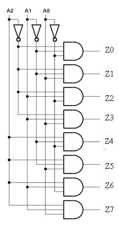
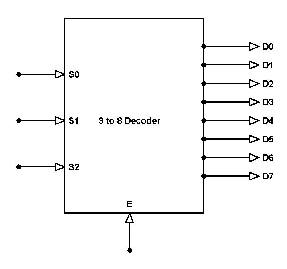
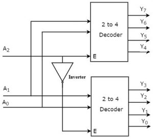
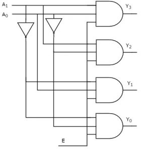
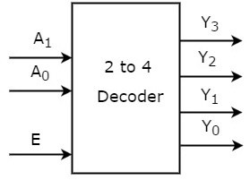
3 To 8 Line Decoder Designing Steps Its Applications
Transmitter and receiver with explanation colour tv transmitter.
. An Encoder is a combinational circuit that performs the reverse operation of Decoder. The working and usage of 83 Encoder is also similar to the 42 Encoder except for the number of input and output pins. Explain how the composite colour signal is formed.
We dont have any answers for this question till now. An Encoder is a combinational circuit that performs the reverse operation of DecoderIt has maximum of 2n input lines and n output lines hence it encodes the. Pal Encoder And Decoder Block Diagram Author.
As this pal encoder and decoder block diagram it ends taking place monster one of the favored book pal encoder and decoder block diagram collections that we have. Were working on getting. It has maximum of 2n input lines and n output lines.
Pal Encoder And Decoder Block Diagram 150 Electronics Projects for Engineering Students. A PAL encoder comprises phase converter 1 first and second low-pass filters 23 a burst signal adder 4 a chrominance subcarrier generator 6 and a modulator 5. Pal Encoder And Decoder Block Diagram SANYO LCD 24XR10F SERVICE MANUAL Pdf Download February 13th 2019 - View and Download Sanyo LCD 24XR10F service manual online.
PDF 51 Consumer Electronics AGC Amplifier. Technical drawings block diagram blue print. Pal Encoder And Decoder Block Diagram Keywords.
This is why you remain. Pal Encoder And Decoder Block Diagram Keywords. Pal Encoder And Decoder Block Diagram Author.
Figure given below is the functional diagram of a PAL coder. The 83 Encoder is also called as Octal to Binary Encoder. Production of Luminance Y and Chrominance U and V signals 2.
About Press Copyright Contact us Creators Advertise Developers Terms Privacy Policy Safety How YouTube works Test new features Press Copyright Contact us Creators. The gamma corrected R G and B signals are matrixed to form the Y and the weighted colour difference signals. High Efficiency Video Coding.
It will produce a binary code.
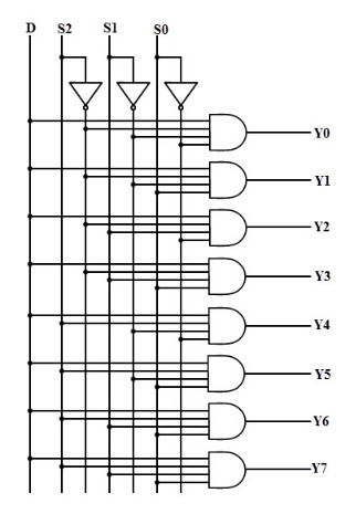
3 To 8 Line Decoder Designing Steps Its Applications
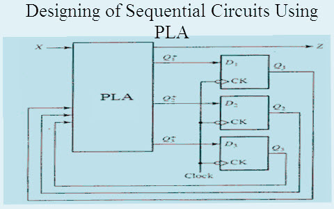
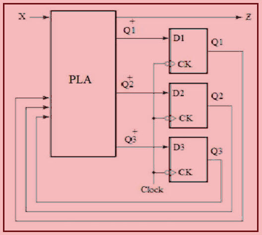
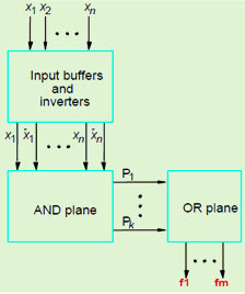
How To Design Sequential Circuit Using Pla Programmable Logic Array
3 To 8 Line Decoder Designing Steps Its Applications
3 To 8 Line Decoder Designing Steps Its Applications

Pal Ntsc Y C Yuv Rgb To Sdi Converter And Decoder Addec 210
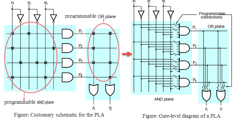
How To Design Sequential Circuit Using Pla Programmable Logic Array
How To Design Sequential Circuit Using Pla Programmable Logic Array
3 To 8 Line Decoder Designing Steps Its Applications
How To Design Sequential Circuit Using Pla Programmable Logic Array
What Is The Difference Between These Below Categories In Digital Camera Quora
Why Do We Add 1 To Find The Median In An Individual Series And A Discrete Frequency Series Quora
3 To 8 Line Decoder Designing Steps Its Applications

Pin Na Doske Free Electronics Circuits

A Few Radio Reviews Shortwave And Other
How To Design Sequential Circuit Using Pla Programmable Logic Array
3 To 8 Line Decoder Designing Steps Its Applications
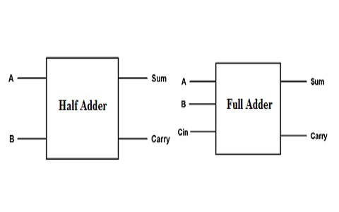
Half Adder And Full Adder Circuit With Truth Tables